
|

|
|
The "V" Style Interlocking Machine and it's use by London Underground History - Illustrations Some of these illustraions are large files so as to retain the fine detail. The diagrams will require scrolling, again so as not to lose detail. | ||
|
Copyright © John Tilly 2010 | ||
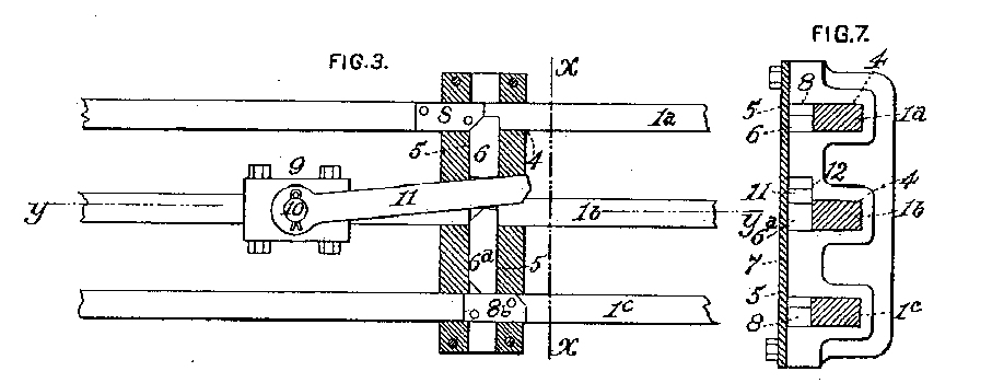 Figure 1: Two of the figures from Hambay's Patent, note the similarities in Dell's Patent. (US) | ||
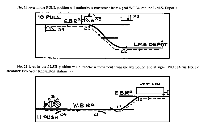 Figure 2: Two illustrations from Traffic Circular No. 25 of 1934 relating to the West Kensington installation, showing typical routes. (LUL) | ||
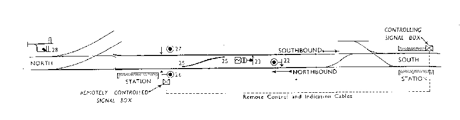 Figure 3: Track Layout at Shoreditch 1943. Shoreditch is the station to the left, and Whitechapel to the right (RG) | ||
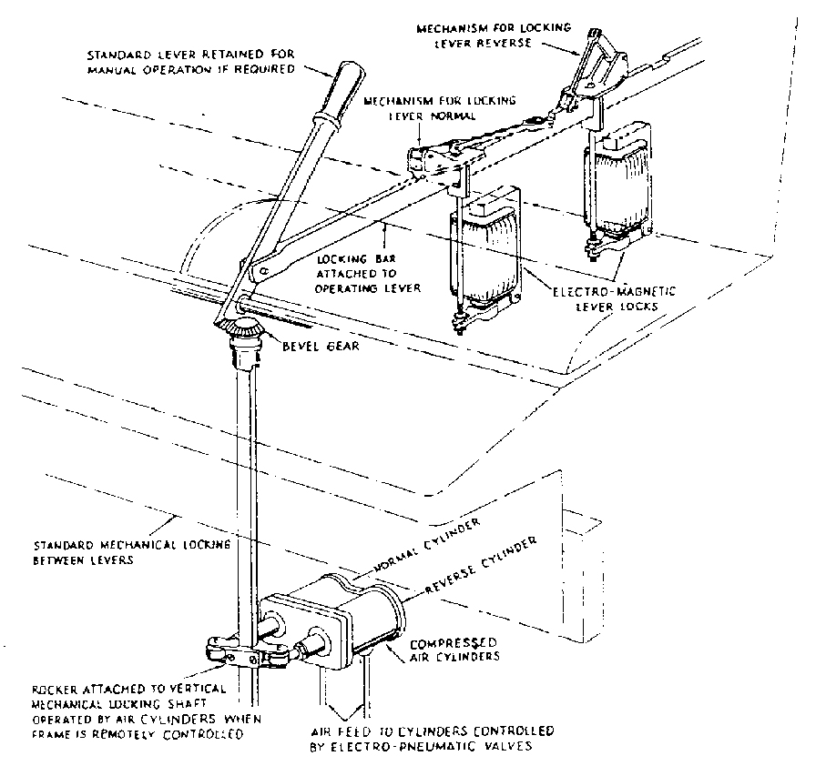 Figure 4: "N" style frame lever motor arrangement. (1RSE) | ||
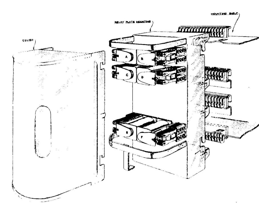 Figure 5: Post Office type 3000 relay "can". (IRSE) | ||
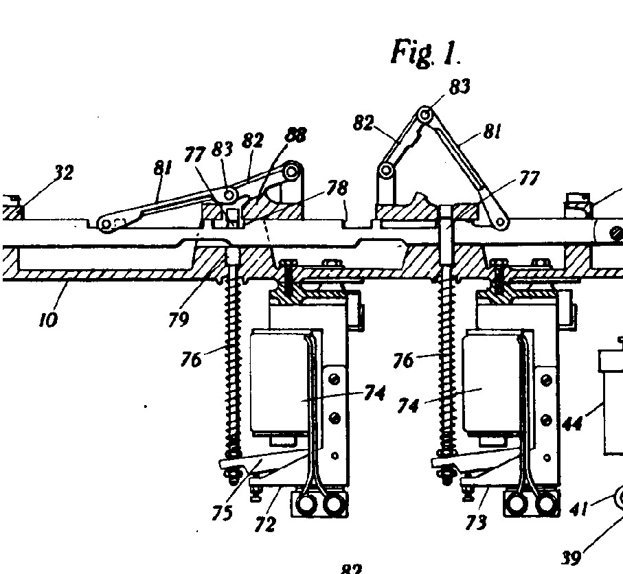 Figure 6: The troublesome mechanical toggle - Left - shown "holding" lever. Right-shown "broken" by electric lock. (PO) | ||
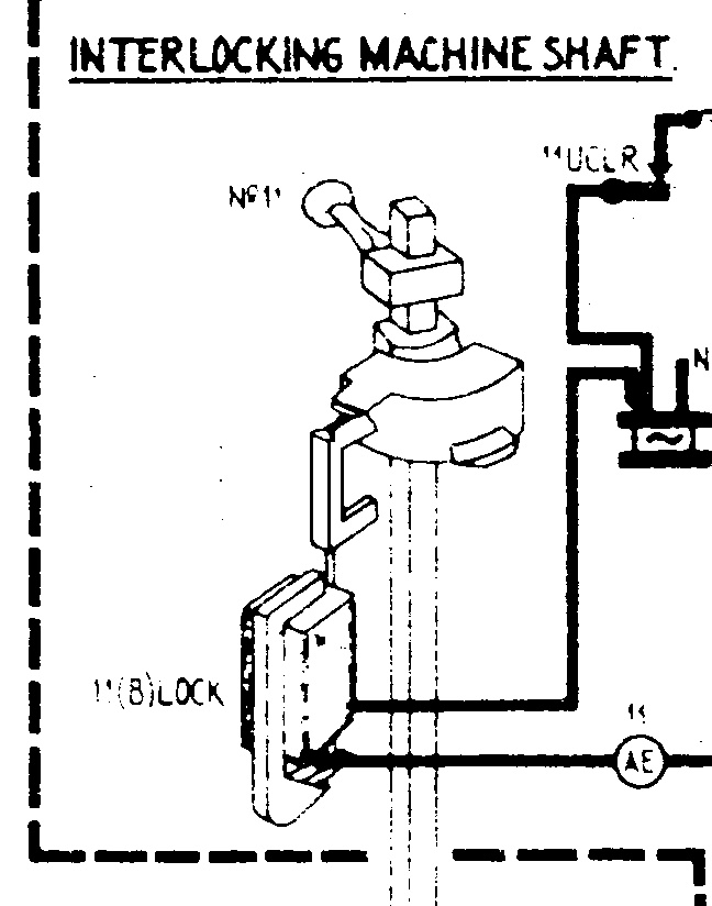 Figure 7: "New" method of engaging electric lock. (3-dimensional view)(LUL) | ||
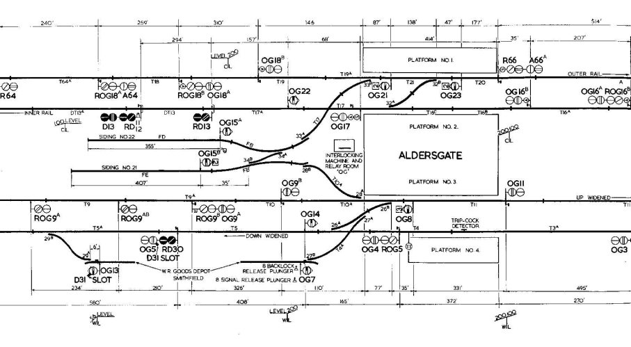 Figure 8: The Traffic Circular diagram showing the layout commissioned at Aldersgate on 18.12.54. (The outer extremities at Farringdon and Moorgate are excluded for the sake of clarity.) (LUL) | ||
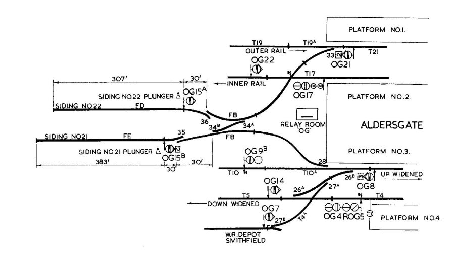 Figure 9: Traffic Circular diagram showing minor track alterations at Aldersgate following the mishap on 24.1.55. (LUL) | ||
| ||

|